Typical Automtive Starter Wiring Diagram - Wiring Diagrams For Cars Trucks Download With How To Guide Obdii365 Com Official Blog : Where a ballast resistor is not used, connect the da plug long wire to the coil + terminal as indicated by the dashed line.
Typical Automtive Starter Wiring Diagram - Wiring Diagrams For Cars Trucks Download With How To Guide Obdii365 Com Official Blog : Where a ballast resistor is not used, connect the da plug long wire to the coil + terminal as indicated by the dashed line.. The wiring diagram for a dol stater is shown below. Tion diagrams, show the actual connection points for the wires to the components and terminals of the controller. View my channel joe electronics schematic for auto and my other channel automotive electronic schematics by joseph for more automotive diagnostics and video. Testfahrer werden durch optische und akustische signale optimal unterstützt. This setup requires the safety wiring system to run through the pto switch and the.
For example, the new garden tractors that have and electic pto and a mow in reverse bypass switch. The standard labeling system will use the first letter to indicate the base color, and the second letter to indicate the stripe color. Figure 4 is a typical automotive wiring diagram that shows a radiator cooling fan circuit. 3 typical car starting system diagram. Automotive electrical diagrams provide symbols that represent circuit component functions.
Comprehensive Power Supply System Designs For Harsh Automotive Environments Consume Minimal Space Preserve Battery Charge Feature Low Emi Analog Devices from www.analog.com Simply take a 6 length of medium gauge wire and strip both ends. For this reason, stranded wire is used when the wire needs to move around frequently, in automotive applications or in appliances for example. A car wiring diagram is a map. The standard labeling system will use the first letter to indicate the base color, and the second letter to indicate the stripe color. Testfahrer werden durch optische und akustische signale optimal unterstützt. I've entered a 2000 toyota camry as the year, make and model we're working on. When working with your model a used stranded wire for the best results. The dol starter comprises an mccb or circuit breaker, contactor and an overload relay for protection.
The starter, which operates with the help of a solenoid, can generate a significant amount of horsepower for a limited time.
Premium color wiring diagrams get premium wiring diagrams that are available for your vehicle that are accessible online right now, purchase full set of complete wiring diagrams so you can have full online access to everything you need including premium wiring diagrams, fuse and component locations, repair information, factory recall information and even tsb's (technical service bulletins). 240 volt, 1 phase motors should use a 2 pole starter. When working with your model a used stranded wire for the best results. Charging circuit starting circuit ignition circuit lighting circuit Starter motor starting system how it heavy duty truck starters 1929 a 6v to 12v wiring diagram 3 typical car t x on 12 volt alternator solenoid the definitive guide converting one wire cj2a page bosch generator ls1 needed voltage regulator pocket bike harness full vincent motorcycle electrics wd45 ammeter question allischalmers forum charging 24v. I've entered a 2000 toyota camry as the year, make and model we're working on. A typical starter solenoid has one small connector for the starter control wire the white connector in the photo and two large terminals. Wiring diagram consists of several in depth illustrations that show the relationship of varied products. Where a ballast resistor is not used, connect the da plug long wire to the coil + terminal as indicated by the dashed line. If one is needed for your car, this is the typical mounting position. Tion diagrams, show the actual connection points for the wires to the components and terminals of the controller. Testfahrer werden durch optische und akustische signale optimal unterstützt. They can be used as a guide when wiring the controller.
I've entered a 2000 toyota camry as the year, make and model we're working on. T1 and t2 are the corresponding motor out connections and should be carried through to the motor. How to read car wiring diagrams short beginners version rustyautos com. Automotive wiring, types of terminals, and wiring diagrams. Two fuses (40 and 10 amps) power the circuit and are directly connected to the vehicle's battery (hot at all times).
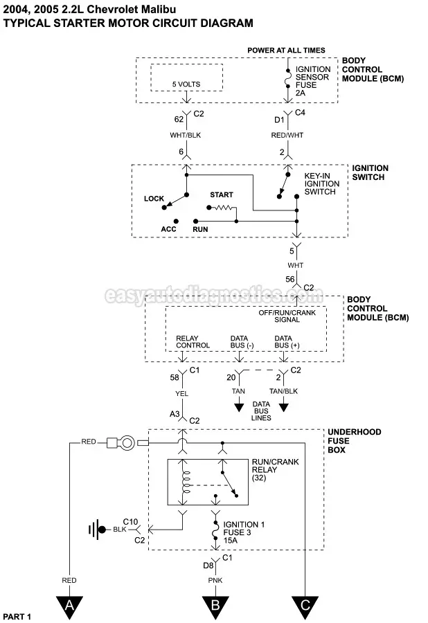
Starter Motor Circuit Wiring Diagram 2004 2005 2 2l Chevrolet Malibu from easyautodiagnostics.com Where a ballast resistor is not used, connect the da plug long wire to the coil + terminal as indicated by the dashed line. Tion diagrams, show the actual connection points for the wires to the components and terminals of the controller. Use the legend to understand what each symbol on the circuit means. The automotive electrical system contains five electrical circuits. Automotive electrical diagrams provide symbols that represent circuit component functions. Sie können das system problemlos anpassen und erweitern. Accuspark wiring diagrams 1929 a 6v to 12v diagram warn full basic ignition system 5 4 8 primary farmall cub 12 volt coil for ford 9n 2n 8n headlight conversion converting one wire alternator your boat msd crane ezgo solenoid systems short course johnson motor cat 6a internal 12vpressor 6 positive ground typical battery. The standard labeling system will use the first letter to indicate the base color, and the second letter to indicate the stripe color.
Automotive wiring, types of terminals, and wiring diagrams.
This setup requires the safety wiring system to run through the pto switch and the. Typical applications are on woodworking machinery, metal sawing machines, and many other machine tools where undervoltage protection is needed to meet safety. How to read car wiring diagrams short beginners version rustyautos com. 91 gas club car wiring diagram bad solenoid on a golf cart 1990 full battery for 2006 buggiesunlimited com 1999 starter generator testing 2003 ds motor 1992 1996 or electric what is it and how 36 volt i need. Sie können das system problemlos anpassen und erweitern. Question 2 uses a wiring diagram that is more complex than the one used for the first question. An example would be the letters ob. 240 volt, 1 phase motors should use a 2 pole starter. Let's take a look a screen shot from a professional shop manual like mitchel's ondemand. Now i can choose the car wiring. For example, the new garden tractors that have and electic pto and a mow in reverse bypass switch. The first generation of nissan altima sedans were produced from 1992 to 1997 in the united states and japan. Ford used only stranded wire.
Two fuses (40 and 10 amps) power the circuit and are directly connected to the vehicle's battery (hot at all times). An example would be the letters ob. The arrows and open terminals are the connections used by people. Security starter relay controlled car starter wiring diagram. Sie können das system problemlos anpassen und erweitern.
Chevy Starter Relay Wiring Diagram Wiring Diagram 154 Scatter from i.pinimg.com Sedan nissan altima second generation produced from 1998 to 2001. Car wiring diagrams are grouped by system. This wiring should not be used on 240 volt circuits. It includes directions and diagrams for different types of wiring strategies along with other items like lights, home windows, and so forth. An example would be the letters ob. For this reason, stranded wire is used when the wire needs to move around frequently, in automotive applications or in appliances for example. Accuspark wiring diagrams 1929 a 6v to 12v diagram warn full basic ignition system 5 4 8 primary farmall cub 12 volt coil for ford 9n 2n 8n headlight conversion converting one wire alternator your boat msd crane ezgo solenoid systems short course johnson motor cat 6a internal 12vpressor 6 positive ground typical battery. These circuits are as follows (fig.
I'm an auto technician for over twenty years, i've always loved the electrical side of auto repair.
The main function of car starting circuit is. View my channel joe electronics schematic for auto and my other channel automotive electronic schematics by joseph for more automotive diagnostics and video. Learn to navigate this systems wiring circuitry and diagram using current flow analysis relay and module operation and neutral switch actuation such as circuit completion. Testfahrer werden durch optische und akustische signale optimal unterstützt. Tion diagrams, show the actual connection points for the wires to the components and terminals of the controller. I've entered a 2000 toyota camry as the year, make and model we're working on. (1) switch, (2) battery, (3) resistor and (4) ground. 240 volt, 1 phase motors should use a 2 pole starter. T1 and t2 are the corresponding motor out connections and should be carried through to the motor. Automotive electrical diagrams provide symbols that represent circuit component functions. Two fuses (40 and 10 amps) power the circuit and are directly connected to the vehicle's battery (hot at all times). The starter, which operates with the help of a solenoid, can generate a significant amount of horsepower for a limited time. Wd45 ammeter question allischalmers forum.


0 Komentar